25+ transfer function block diagram examples
Transfer Function Block Diagram. 1 Let us explain the concept of poles and zeros of transfer function through an example.
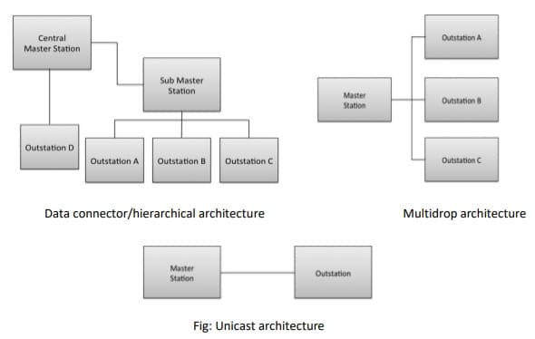
Dnp3 Protocol Architecture Working Differences Applications
Step 3 Get the.
. What we will do next will be to name the outputs of the comparators the circles. 2012 PDH Online PDH. G in cascade is given in Fig.
The block diagram of Figure 3-44 can be modified to that shown in Figure 3-45a. Block diagrams consist of Blocks these represent. 7-11 The output transform for any block is equal to the input transform multiplied by the.
Block diagram shown in Figure 3-44. Block Diagram Reduction Solved Example 1Topics discussed1. Transfer functions and their corresponding block diagrams are shown as a reference for how to manipulate or construct one from the other.
The transfer function of the system Gs IsVs the ratio of output to input. Consider the following equations in Transfer Functions Block Diagrams. Step 2 Repeat step 1 for remaining inputs.
This permits the signal to proceed unaltered along several different paths to several destinations. Consider the block diagram shown in the following figure. Xl Xÿ Xn Fig.
Therefore the negative feedback closed loop transfer function is fracGs1GsHs This means we can represent the negative feedback connection of two blocks with a single block. The block diagram for n transfer functions G1Ga. PDHonline Course E138 4 PDH Automatic Control Systems - Part I.
Multiplication of transfer functions convolution of impulse responses u u composition y y A B BA ramifications. Block Diagrams and Transfer Functions Instructor. Step 1 Find the transfer function of block diagram by considering one input at a time and make the remaining inputs as zero.
Shih-Min Hsu PhD PE. Solved Example based on the calculation of the overall transfer function of a. Figure 3-46 Block diagram of a system.
Can manipulate block diagrams with transfer functions as if they were. Note The transfer function present in this single block is the transfer function of the overall block diagram. Webb ESE 499 3 Block Diagrams In the introductory section we saw examples of block diagrams to represent systems eg.
As you can see in the previous diagram we add names to the outputs now that we have the output A and the.
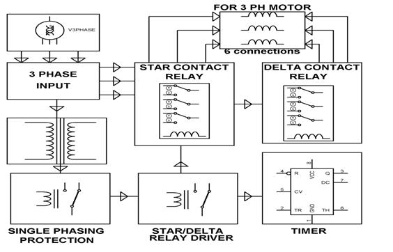
3 Phase Induction Motor With Help Of Industrial Star Delta Starter
![]()
Open Loop Control System Block Diagram Working Its Applications
Process Intensification Of Element Extraction Using Centrifugal Contactors In The Nuclear Fuel Cycle Chemical Society Reviews Rsc Publishing Doi 10 1039 D2cs00192f

Top 25 Computer Architecture Interview Questions And Answers
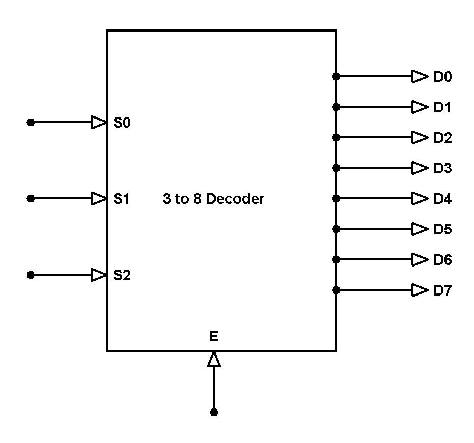
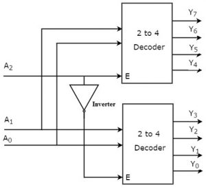
3 To 8 Line Decoder Designing Steps Its Applications

Top 25 Computer Architecture Interview Questions And Answers

Nrf24l01 Single Chip Transceiver A Basic Overview Video
Solved Find The Inverse Laplace Transform Of The Following Functions Course Hero
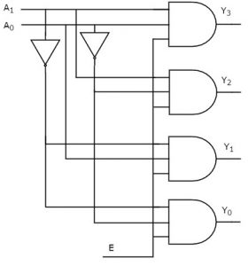
3 To 8 Line Decoder Designing Steps Its Applications
3 To 8 Line Decoder Designing Steps Its Applications
What Are The Control Statements In C Language Quora

Aws Lambda Aws Compute Blog
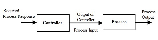
Open Loop Control System Block Diagram Working Its Applications

Implementing A Pid Controller On An Arduino Board Arduino Pid Controller Control Systems Engineering
Process Intensification Of Element Extraction Using Centrifugal Contactors In The Nuclear Fuel Cycle Chemical Society Reviews Rsc Publishing Doi 10 1039 D2cs00192f

Dual Clock Asynchronous Fifo In Systemverilog Verilog Pro
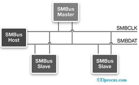
Smbus Working Differences Timing Diagram And Its Applications